
How should an RF surge protector be selected and installed?
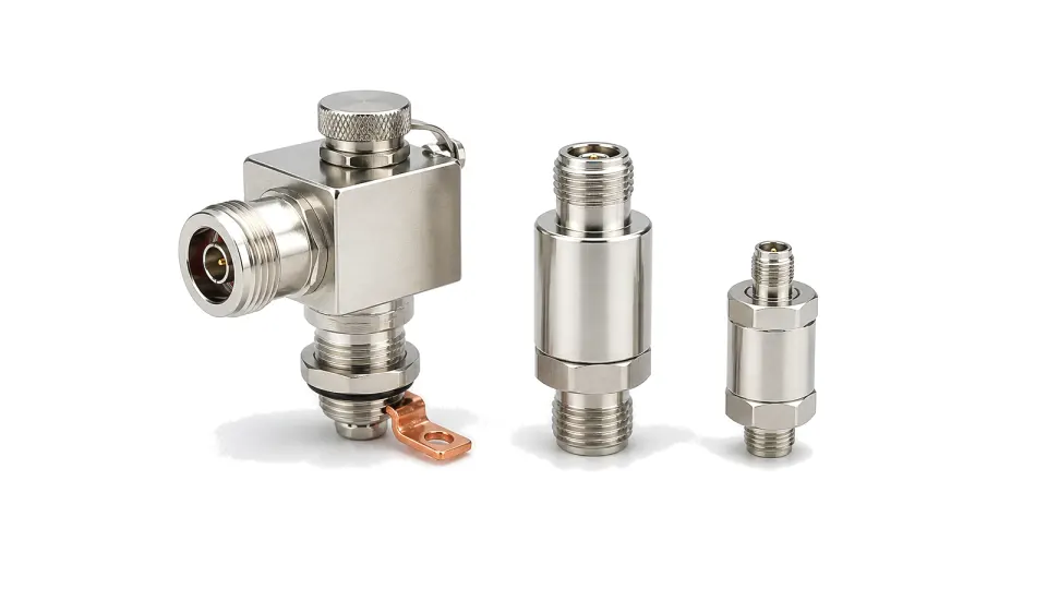
Choose the protection topology from the actual coaxial interface, RF band, peak line voltage, transmitted power, DC or control-current path and defined surge waveform, then mount it at the protection-zone boundary with a short, low-inductance bond to the equipotential ground. A coaxial protector is one part of a site protection system, not a guarantee that equipment will survive a direct strike. Its job is to provide a controlled path between the centre conductor, outer conductor and local bonding network before the transient reaches the protected port. A device can carry the wanted RF signal yet still be unsuitable because its sparkover voltage, residual pulse, grounding path, passive intermodulation or service arrangement does not match the installation.
Define the threat, interface and wanted signals
Mark the boundary between the exposed antenna or feeder and the protected equipment area. Record connector series, 50 or 75 ohm impedance, operating and guard bands, transmit peak and average power, receive sensitivity, acceptable insertion loss and return loss, and any passive-intermodulation limit. Determine whether the coax must pass DC, low-frequency control or bias current. Quantify the maximum continuous conductor voltage, including RF peak voltage and remote-power tolerance. A DC-blocked protector cannot serve a powered antenna path; a straight-through GDT design must not fire or remain conducting during valid RF and DC operation.
Compare protection topology and impulse data on the same basis
Gas-discharge-tube protectors are broadband and may pass DC, but their static and impulse sparkover, follow-current behavior, cartridge life and residual energy require coordination with the equipment port. Quarter-wave or shorting-stub designs can offer low residual voltage in a defined RF band, but bandwidth and DC behavior depend on the mechanical filter. Hybrid stages add finer clamping at the cost of more topology-specific limits. Compare nominal discharge current only when the waveform is identical: an 8/20 microsecond induced-surge rating is not interchangeable with a 10/350 microsecond partial-lightning-current rating. Also compare impulse sparkover, residual voltage, RF power, VSWR, insertion loss, PIM, environmental seal and replaceability.
Install at the bond boundary and verify after stress
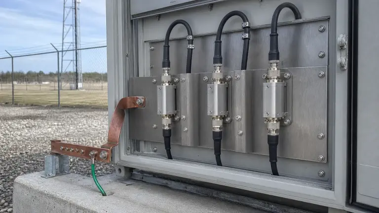
Use a conductive bulkhead or the shortest specified ground connection at the cable entry; a long pigtail adds inductive voltage exactly when surge current rises fastest. Keep protected and unprotected cable routes separated, respect port direction where specified, weather-seal the exposed interface, apply connector and mounting torque, and avoid cable strain. Coordinate the coax protector with antenna bonding, feeder grounding kits, mains and data-line SPDs and any downstream receiver limiter. Before service, record S11, S21, DC continuity or isolation and PIM where relevant. After a severe event, inspect for arcing, heat or connector damage and repeat breakdown or cartridge, return-loss and insertion-loss checks under the maker's procedure.
- Protection-zone boundary, exposed feeder route and equipotential bond point
- Connector, impedance, frequency band, insertion loss, return loss and PIM
- Peak RF power, maximum line voltage, DC pass or block and control current
- GDT, quarter-wave, hybrid or other topology with stated residual behavior
- Impulse current and voltage ratings with their exact 8/20 or 10/350 waveform
- Bulkhead grounding, sealing, service access and post-event retest plan
Category boundary
This category covers coaxial RF surge protectors and lightning arrestors installed in antenna, feeder and RF cable paths, including gas-discharge-tube, quarter-wave and hybrid variants. Building air terminals, AC or DC mains SPDs, data-line protectors, ordinary DC blocks, receiver limiters and the complete grounding or lightning-protection system are separate entities and require their own acceptance criteria.