
RF MMIC Amplifiers
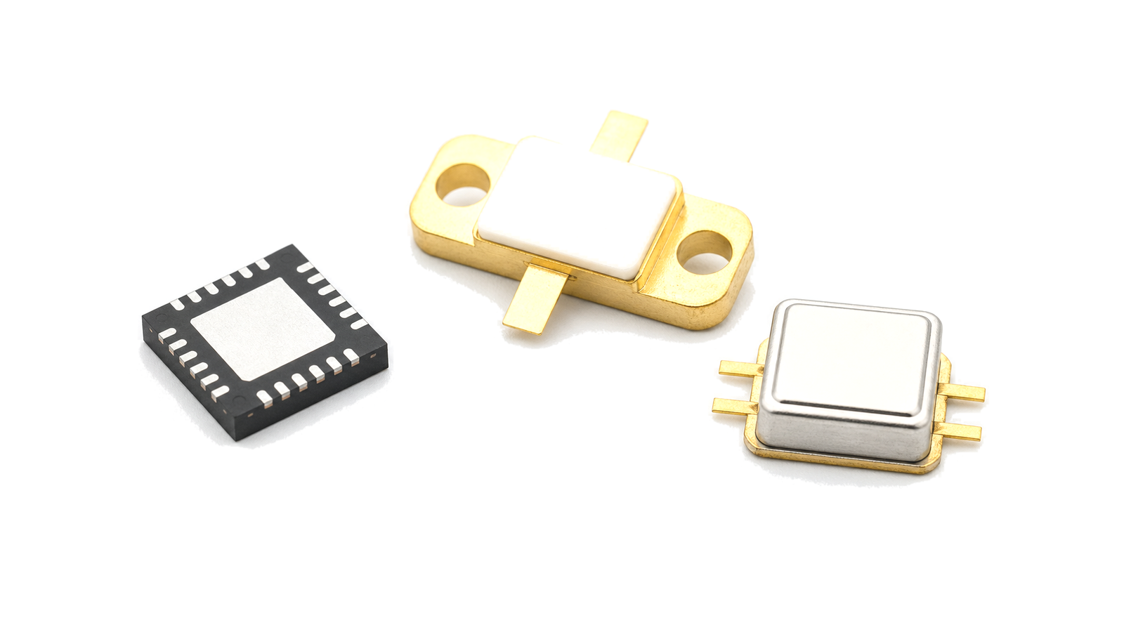
RF MMIC amplifiers place one or more microwave gain stages on a monolithic integrated circuit. They are used when a design needs compact layout, repeatable RF behavior and fewer external matching parts than a discrete amplifier chain.
Typical use
These amplifiers appear in receiver front ends, driver paths, test instruments, phased-array channels, microwave modules and embedded RF assemblies where package size, bias current and gain flatness affect the surrounding layout.
Engineering data
- Frequency range, small-signal gain, noise figure, P1dB, OIP3 and gain flatness describe RF behavior.
- Bias voltage, current consumption, package style and thermal pad layout define board integration.
- S-parameters, recommended matching and stability data are normally reviewed with the module layout.
Treat the semiconductor, board and measurement plane as one controlled decision
- RF MMIC Amplifiers supplier / RF MMIC Amplifiers manufacturer
- Treat bare die, traceability and change control as engineering interfaces For bare die, define ESD control, sealed storage, dry environment after opening when required, cleanliness, pickup area, die orientation, backside condition, attach material and thickness, cure, substrate proximity, wire or ribbon material, bond length and loop, pull or shear inspection and visual criteria....
- RF MMIC Amplifiers technical specifications
- Freeze function, conditions and evidence class before comparing parts Name the signal-chain role first: low-noise gain, driver or power gain, frequency conversion, switching, attenuation, phase control, detection, synthesis, transceiver function, protection or integrated passive behavior. Mark every RF, LO, IF, DC, control, timing and thermal interface....
- RF MMIC Amplifiers selection guide
- Freeze function, conditions and evidence class before comparing parts Name the signal-chain role first: low-noise gain, driver or power gain, frequency conversion, switching, attenuation, phase control, detection, synthesis, transceiver function, protection or integrated passive behavior. Mark every RF, LO, IF, DC, control, timing and thermal interface....
- RF MMIC Amplifiers test and verification
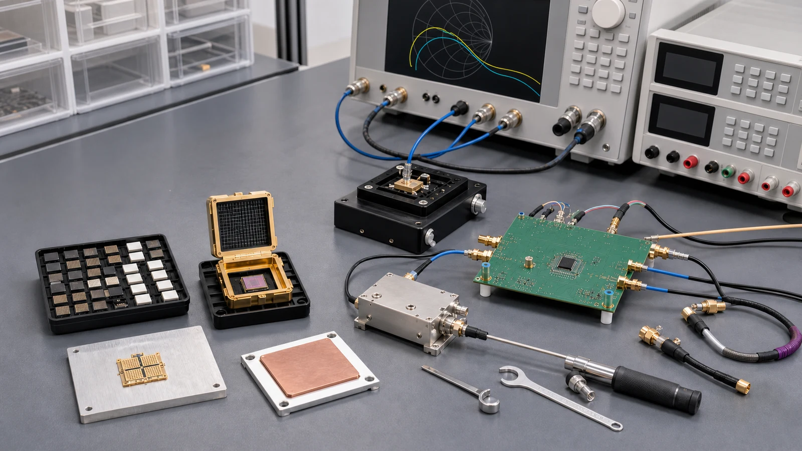
- Move the calibrated plane to the DUT and verify production-relevant states Define where the VNA, noise, power, linearity, phase-noise or switching measurement is calibrated and what remains between that plane and the semiconductor....
How to Select and Verify RF ICs, MMICs and Semiconductor Devices
Turn an RF semiconductor shortlist into an executable design decision by controlling datasheet conditions, reference planes, stability, bias and protection, package and PCB interfaces, thermal limits, fixture removal, production spread and acceptance evidence.