
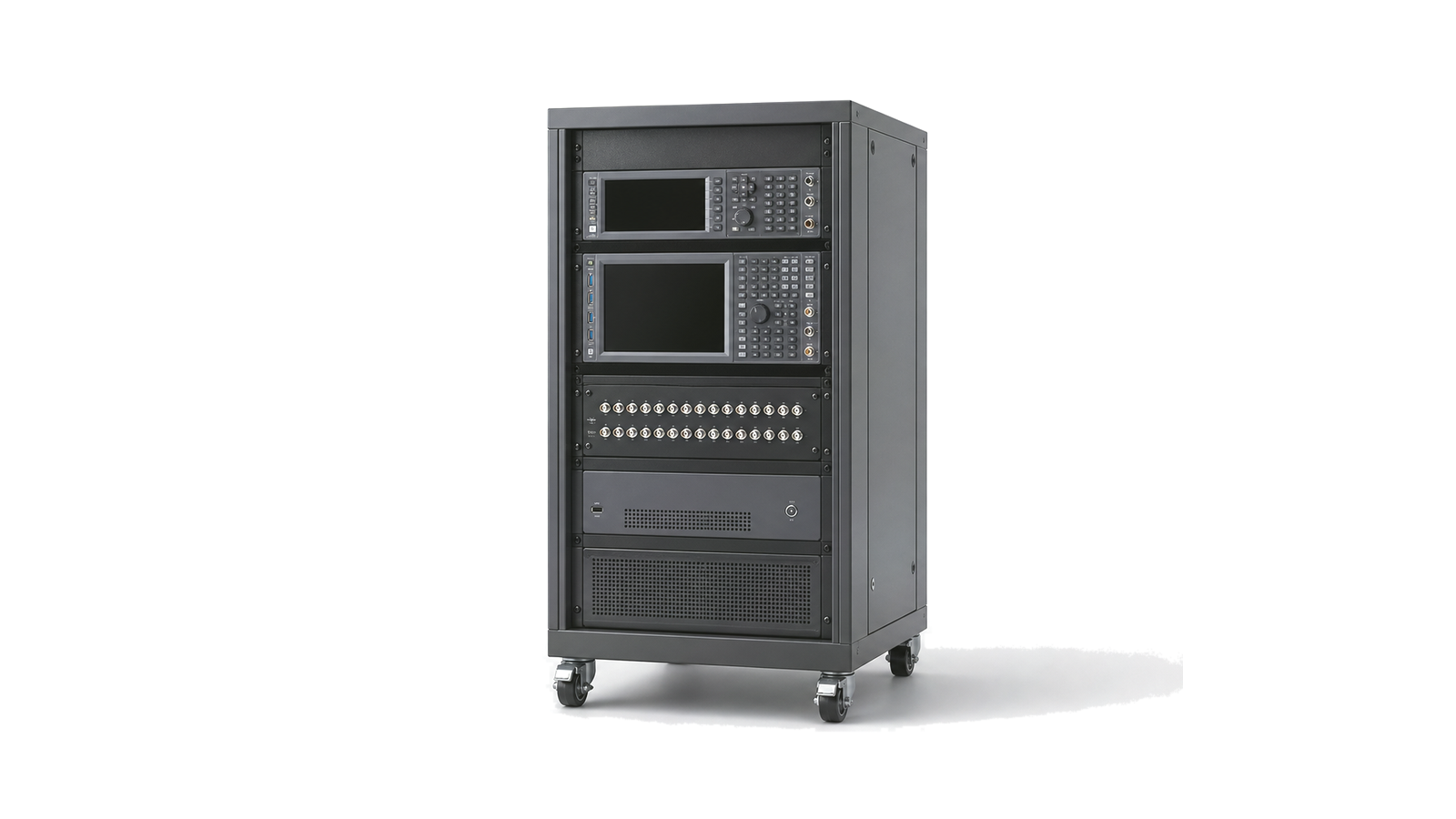
What must be defined before an automated RF test rack is specified?
Define the DUT variants and interfaces, required stimulus and measurements, frequency and power envelope, routing states and reference planes, uncertainty and guard bands, calibration method, cycle time and concurrency, handler or fixture sequence, safety, software ownership, result schema, maintenance plan and station acceptance criteria. A rack is a measurement system, not a furniture list. Instrument specifications can be lost through switching, cables and fixtures; a fast measurement can still produce a slow station; and an unversioned calibration or routing state can make passing data impossible to reproduce. Architecture must start from the test requirement and production decision, then flow into hardware, software and mechanical design.
Translate the DUT requirement into a test and routing matrix
List every DUT family, connector, power state, firmware state, waveform and required result. For each test, state source and receiver resources, frequency, bandwidth, level, modulation, accuracy, settling, trigger, direction and pass/fail decision. Build a routing matrix that identifies concurrent and mutually exclusive paths, terminations, attenuators, couplers, bias tees, loads and protection. Put calibration and verification standards on the same matrix. This exposes port-count growth, switch conflicts and hidden re-cabling before rack layout begins.
Close RF performance and measurement uncertainty at the DUT plane
Set the measurement reference plane at the DUT fixture and budget generator and analyzer accuracy, cable and switch loss, mismatch, isolation, repeatability, noise, compression and drift. Define where path-loss correction is measured, how temperature and connector cycles are handled, and which uncertainty terms enter each guard band. High-power or noise-figure paths need separate protection, thermal and calibration logic. The rack must demonstrate that its uncertainty supports the product limit; repeating an instrument data sheet does not establish system capability.
Engineer throughput, software, safety and data as one system
Calculate cycle time from fixture motion, DUT communication, path switching, settling, acquisition, processing, retries and data transfer, not measurement time alone. Decide whether parallel sites share instruments and how resource contention is scheduled. Specify interlocks, emergency stop, power distribution, grounding, cooling, RF exposure controls and safe discharge. Software needs versioned sequences, instrument and switch state control, error recovery, simulation hooks, user roles and a result schema tied to DUT serial number, limits, calibration state and station configuration.
Plan calibration, maintainability and production acceptance
Separate daily confidence checks, path verification, periodic calibration and repair replacement. Provide accessible standards, continuity checks, loopback or golden-unit routines and limits for drift. Rack drawings must cover airflow, cable bend radius, connector access, spare capacity, lifting and service zones. Factory acceptance and site acceptance should use traceable artifacts and known DUTs to prove measurement correlation, repeatability, cycle time, fail handling, data integrity, safety and recovery after power, network or instrument faults. Record software, firmware, calibration and wiring revisions together.
- DUT variants, interfaces, states, test coverage, limits and guard-band ownership
- Frequency, bandwidth, power, routing states, reference planes, losses and isolation
- Uncertainty budget, calibration standards, verification interval and correlation method
- Cycle time, multisite scheduling, fixture motion, settling and retry policy
- Power, grounding, cooling, interlocks, RF safety, service access and spare capacity
- Software versions, control interfaces, result schema, traceability and FAT/SAT evidence
Category boundary
This category covers rack-based automated RF test systems that integrate multiple instruments, switching and signal conditioning, DUT interfaces or fixtures, rack power and safety, control software, calibration and result handling as one station. It includes engineering validation, qualification and production racks. It excludes standalone instruments, switch matrices or fixtures sold as separate components, empty rack infrastructure, wafer probers and handlers, shielded chambers by themselves, and complete production cells whose main scope is material handling rather than RF measurement.